


Whitepapers
HRSG Tube Failure Statistics
Tetra Engineering Group, Inc. (TETRA) has assisted the owners of natural gas-fired combined cycle plants with ...


Tube thinning caused by flow-accelerated corrosion (FAC) is one of the most frequent causes of failure in the heat exchanger tubes of heat recovery steam generators (HRSGs), with localized progressive thinning of tube walls eventually leading to rupture and leaks. Any carbon steel tubes that carry water or wet steam are potentially at risk.
The overall mechanisms of FAC, wherein the protective magnetite layer of the base metal is dissolved at an accelerated rate, are relatively well-understood [1] [2] [3] [4] [5] [6]. Key factors controlling magnetite dissolution are temperature, water chemistry and fluid mass transfer rate. Two strategies for avoiding or at least greatly reducing the problem in operating plants are available; the easiest in most cases is to change the water chemistry by raising pH and creating an oxidizing environment. If this is not sufficient or if other factors (such presence of copper-alloy components in steam cycle) prevent this, then it may be necessary to replace carbon steel tube sections encountering wear with a more resistant material, namely low-alloy steel containing some chrome.
One area in the HRSG that is prone to FAC is the low-pressure evaporator (LPEVAP). Fluid temperatures here are often at or near the peak of magnetite dissolution (150°C), flow rates can be high and water chemistry pH control is typically all-volatile. The most common volatile alkalizer is ammonia. In that case the pH is lowered in two-phase regions because ammonia preferentially migrates to the steam phase, i.e. the distribution ratio of ammonia is greater than 1. This is also true for certain amines that are used as alternatives to ammonia.
Even when water chemistry and process conditions are set by design to minimize the risk of FAC, experience shows that localized thinning can still be observed in the LPEVAP modules, particularly in the two-phase region near the outlet header and in the risers to LP drum. An analysis of data from the LPEVAP modules in different plants pointed out that fluid velocities in the upper section of the tube and the riser can be very high in some HRSG designs [7] . Very high two-phase flow velocities will mechanically damage the magnetite layer and increase the FAC rate. At some point mechanical damage to magnetite will become the driving factor instead of chemistry or temperature. As velocities increase further then direct erosion of the base metal will ensue [8]. If the two-phase fluid has a high vapor fraction and a high velocity, the entrained water droplets will erode surfaces. This form of erosion is commonly labeled Liquid Droplet Impingement (LDI) [9]. Affected areas are pipe bends and locations after flow perturbations, or wherever there are very high local flow velocities [10]. The droplets contained in the two-phase mixture do not follow changes in the bulk flow direction and impinge against the pipe wall in the “line of sight” with a force that is dependent on droplet size, velocity and angle of impact [11] [12]. The wear mechanism at work is important in that while FAC can be controlled by keeping the water chemistry (pH and DO) within the appropriate control band, mechanical erosion cannot. Only a change to flow geometry and/or liquid phase flow velocities would lower the damage rate [3] [13] [14] [15]. Earlier work involving field measurements and simulations with a number of different LP evaporator designs from operating plants has shown that bulk flow velocities are certainly a factor in the risk of thinning occurring. A design limit of no more than 10m/sec was suggested for the LPEVAP tube flow velocity [16]. A mechanical erosion (or LDI) component was postulated to explain very rapid thinning at some locations.
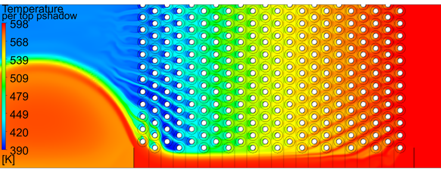
It has been observed that wear rates are generally much higher at the edge of the tube modules, causign failures to occur in a very short (<10.000 hours) period time. The mechanism is commonly attributed to be “gas bypassing” along the edge of the HRSG duct. Given that water chemistry and fluid temperatures are essentially identical in all tubes of a given row, the phenomenon is assumed to be due to changes in fluid velocity between individual tubes. The actual effect was shown by Tetra in a recent technical paper [17]. Figure 1 shows the temperature distribution at a horizontal plane between the fins. There is significant bypass flow between the edge tubes and the duct wall. Variations in heat load imputed by the exhaust gas is the driving factor in differing wear rates within a given tube row. The CFD gas flow profiles indicate that the distribution could lead to much higher wear in the edge tubes and immediately adjoining tubes of rows 3 and 4.
[1] O. Jonas, "Flow-Accelerated Corrosion & Cavitation," Water & Wastes Digest, January 2009.
[2] R. G. Keck, Prediction and Mitigation of Erosive-Corrosive Wear in Steam Extraction Piping Systems, PHD Thesis for the Massachusetts Institute of Technology, 1987.
[3] W. Kastner, N. Henzel and B. Stellwag, "Erosion Corrosion in Power Plants - Research Work, Plant Experience and Predictive Code," in Third International Topical Meeting on Nuclear Power Plant Thermal Hydraulics and Operations, Seoul, Korea, 1988.
[4] D. Zinemanas and A. Herszage, "Flow Accelerated Corrosion: Flow field and mass transport in bifurcations and nozzles," 2008.
[5] R. B. Dooley, R. M. Tilley, V. K. Chexal , J. S. Horowitz and D. P. Munson, "Guidelines for Controlling Flow-Accelerated Corrosion in Fossil Plants," Palo Alto, California, USA, 1997.
[6] S. Uchida, M. Naitoh, H. Okada, Y. Uehara, S. Koshizuka, R. Svoboda and D. Lister, "Effects of Water Chemistry on Flow Accelerated Corrosion and Liquid Droplet Impingement Accelerated Corrosion," Power Plant Chemistry, vol. 11, no. 12, 2009.
[7] J. Malloy, M. Graham, M. Taylor, A. Fabricius and D. Moelling, "Evaluating Relative Contributions of FAC and LDI To Pipe Thinning in HRSG Evaporator Tubes- 240513 Final".
[8] S. Koshizuka, M. Naitoh, S. Uchida and H. Okada, "Evaluation Procedures for Wall Thinning due to Flow Accelerated Corrosion and Liquid Droplet Impingement," in International Symposium on the Ageing Management & Maintenance of Nuclear Power Plants, 2010.
[9] J. Horowitz, "Recommendations for Controlling Cavitation, Flashing, Liquid Droplet Impingement, and Solid Particle Erosion in Nuclear Power Plant Piping Systems," 2004.
[10] N. A. Barton, "Erosion in Elbows in Hydrocarbon Production Systems: Review Document," Caerphilly, Wales, UK, 2003.
[11] Y. Higashi, T. Narabayashi, Y. Shimazu and M. Tsuji, "Study on pipe wastage mechanism by Liquid Droplet Impingement Erosion," in The International Congress on Advances in Nuclear Power Plants (ICAPP), Tokyo, Japan, 2009.
[12] "Recommended Practice - Erosive Wear in Piping Sytems," 2007.
[13] N. Henzel, D. C. Crosby and S. R. Eley, "Erosion/Corrosion in Power Plants Single- and Two-Phase Flow Experience, Prediction, NDE Management".
[14] W. Kastner and K. Riedle, "Empirical Model for the Calculation of Material Losses due to Corrosion Erosion," VGB Kraftwerkstechnik 86, no. 12, December 1986.
[15] W. Kastner, M. Erve, N. Henzel and B. Stellwag, "Calculation Code for Erosion Corrosion Induced Wall Thinning in Piping Systems," Nuclear Engineering and Design, no. 119, 1990.
[16] J. Malloy, M. Graham, M. Taylor, A. Fabricius and D. Moelling, "Design Factors for Avoiding FAC and Erosion in HRSG Low-Pressure Evaporators".
[17] J. Malloy, J. Rusaas, M.Taylor. Understanding Variations in Flow-Accelerated Corrosion Wear Rates in HRSG Evaporator Tubes. International Conference on Flow Accelerated Corrosion, Lille, France, May 2016.
Stay up to date and refer to our large collection of technical white papers and articles

Tetra Engineering Group, Inc. (TETRA) has assisted the owners of natural gas-fired combined cycle plants with ...


